-
Be sure to read this post! Beware of scammers. https://www.indianagunowners.com/threads/classifieds-new-online-payment-guidelines-rules-paypal-venmo-zelle-etc.511734/

You are using an out of date browser. It may not display this or other websites correctly.
You should upgrade or use an alternative browser.
You should upgrade or use an alternative browser.
Machining Glock slide from scratch
- Thread starter SPOOK331945
- Start date
The #1 community for Gun Owners in Indiana
Member Benefits:
Fewer Ads! Discuss all aspects of firearm ownership Discuss anti-gun legislation Buy, sell, and trade in the classified section Chat with Local gun shops, ranges, trainers & other businesses Discover free outdoor shooting areas View up to date on firearm-related events Share photos & video with other members ...and so much more!
Member Benefits:

")
It looks like he appended this to the OPs quoted post, instead of typing text outside of the quote brackets:
"mind sharing the part numbers of the cutters you used. Particularly interested in the carbide you used for the rail slide groove. Excellent work BTW"
"mind sharing the part numbers of the cutters you used. Particularly interested in the carbide you used for the rail slide groove. Excellent work BTW"
Thanks. I went ahead and edited it. I've done the same thing with the new system.It looks like he appended this to the OPs quoted post, instead of typing text outside of the quote brackets:
"mind sharing the part numbers of the cutters you used. Particularly interested in the carbide you used for the rail slide groove. Excellent work BTW"
SPOOK331945
Sharpshooter
mind sharing the part numbers of the cutters you used. Particularly interested in the carbide you used for the rail slide groove. Excellent work BTW
Let me see if I can find the cutter in my tool box. I don't remember off the top of my head what it was. I know that it was a t-slot cutter from Harvey Tool. I did however put it in a spin fixture and ground it down a touch on the neck to get the depth I needed. Diamond wheel of course. Harvey will probably have a cutter that work without modification. That was a miscalculation on my part when machining it, and trying to avoid spending another $150-200 on another cutter...
SPOOK331945
Sharpshooter
If Americans really value their Second Amendment, they should start cutting steel. We're coming to that point...Very very impressive and a job (IMHO) well done, you must be the guy Biden is afraid of, a civilian gun maker.
Well now that this is opened up. How hard would it be for you to make stainless steel frame for your glock slide? I wonder how that would work and look?If Americans really value their Second Amendment, they should start cutting steel. We're coming to that point...
SPOOK331945
Sharpshooter
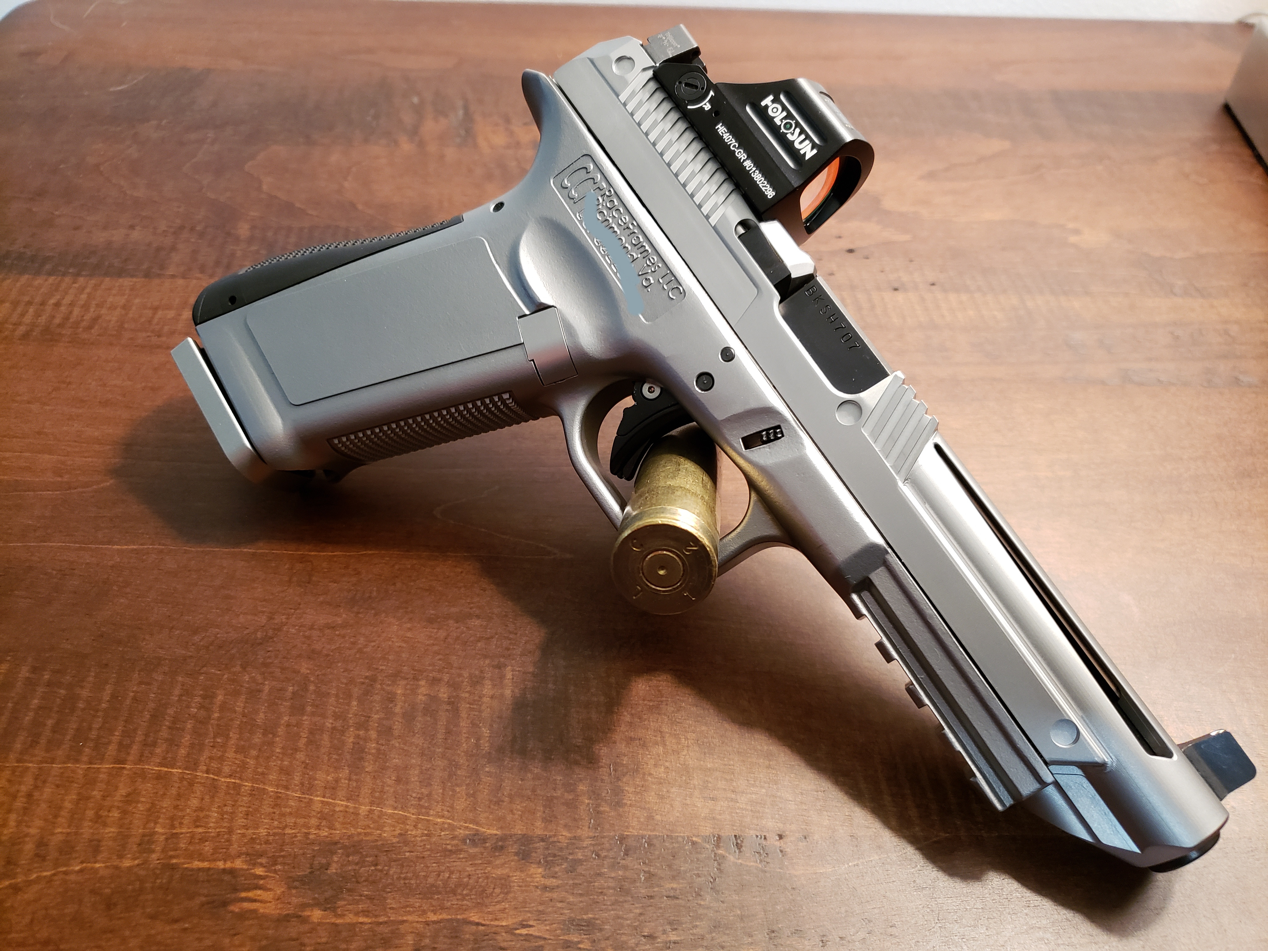
Pretty difficult.. One way I approach it is, what was the original manufacturing design intent? Was it intended to be machined, or molded, or stamped? Looking at a glock frame it was intended to be molded, so with that said it would be very difficult to mimic the design without using some form of MIMS, molding, casting, multi-axis CNC etc... Traditional manual machining methods would be difficult, next to impossible really, to mimic the design. Could it be redesigned to accommodate the manufacturing methods used on manual machine? Sure, why not? But you may resemble more of a 1911 frame by the time you're done. That's why a 1911 looks the way it does. When Mr. Browning designed it, the design intent was to be manufactured on manual machines, obviously because of that being the only form of machining for that time period.Well now that this is opened up. How hard would it be for you to make stainless steel frame for your glock slide? I wonder how that would work and look?
In short, it depends on how creative you are and how deep your pocket book is.
But, to answer what a stainless steel glock frame would look like. Here you go. keep in mind this is NOT my design nor will I take credit for it. It was a company called CCF race frames a few years back. They offered them in stainless, aluminum and titanium. I believe they did it with a MIMS system of some kind. This is one put together a couple years ago.
P.S. Another note on design intent. They recommend using factory plastic guide rods in the CCF frames because the steel doesn't move/absorb energy as the plastic frames do. Like dry firing a bow, the energy has to be displaced somewhere. In this case, steel frame and steel guide rod. One has to give eventually.... Most likely catastrophic permanent deformation...
Great reply thank you for all that good information. So in some cases metal frames would actually take a pounding. Plus Glock was designed from the beginning to use the polymer frames. Where as CZ, and JMB 1911's are designed from metal frames except my CZ P10F of course.Pretty difficult.. One way I approach it is, what was the original manufacturing design intent? Was it intended to be machined, or molded, or stamped? Looking at a glock frame it was intended to be molded, so with that said it would be very difficult to mimic the design without using some form of MIMS, molding, casting, multi-axis CNC etc... Traditional manual machining methods would be difficult, next to impossible really, to mimic the design. Could it be redesigned to accommodate the manufacturing methods used on manual machine? Sure, why not? But you may resemble more of a 1911 frame by the time you're done. That's why a 1911 looks the way it does. When Mr. Browning designed it, the design intent was to be manufactured on manual machines, obviously because of that being the only form of machining for that time period.
In short, it depends on how creative you are and how deep your pocket book is.
But, to answer what a stainless steel glock frame would look like. Here you go. keep in mind this is NOT my design nor will I take credit for it. It was a company called CCF race frames a few years back. They offered them in stainless, aluminum and titanium. I believe they did it with a MIMS system of some kind. This is one put together a couple years ago.
P.S. Another note on design intent. They recommend using factory plastic guide rods in the CCF frames because the steel doesn't move/absorb energy as the plastic frames do. Like dry firing a bow, the energy has to be displaced somewhere. In this case, steel frame and steel guide rod. One has to give eventually.... Most likely catastrophic permanent deformation...
Again thank you for the time you took to educate me.
Yup. Pretty cool. I'm in plastic injection molding so I have a little understanding about the restrictions in injection molding and how complex a mold gets in order to make something and then be able to get it out of the press.
SPOOK331945
Sharpshooter
Yup. Pretty cool. I'm in plastic injection molding so I have a little understanding about the restrictions in injection molding and how complex a mold gets in order to make something and then be able to get it out of the press.
You're welcome!Great reply thank you for all that good information. So in some cases metal frames would actually take a pounding. Plus Glock was designed from the beginning to use the polymer frames. Where as CZ, and JMB 1911's are designed from metal frames except my CZ P10F of course.
Again thank you for the time you took to educate me.
Had a bit of time in molding and stamping. Prefer stamping personally.
Do you all think this would be possible on a 3 axis CNC?
I am working on building a V1 Engineering mostly printed CNC machine. It is what you think, a mostly 3d printed CNC machine with EMT conduit and 3d printer stepper motors for motion control. It probably won't be able to hold .0002 tolerances but it's also a home grade steel-capable CNC machine for under $1000.
I am working on building a V1 Engineering mostly printed CNC machine. It is what you think, a mostly 3d printed CNC machine with EMT conduit and 3d printer stepper motors for motion control. It probably won't be able to hold .0002 tolerances but it's also a home grade steel-capable CNC machine for under $1000.
As a master machinist, (this is in reference to a frame) possibly, you would definitely need a tombstone mounted on a 4th axis, or your gonna have a crap load of time in building fixtures and set up.Do you all think this would be possible on a 3 axis CNC?
I am working on building a V1 Engineering mostly printed CNC machine. It is what you think, a mostly 3d printed CNC machine with EMT conduit and 3d printer stepper motors for motion control. It probably won't be able to hold .0002 tolerances but it's also a home grade steel-capable CNC machine for under $1000.
A slide or similar item that can be held in a vise or simple fixture, your probably gonna have better success with.
The V1 machine is good for the hobbyists, but lack rigidity, there for slower speeds & feeds equalling small cuts, lots of time to do small operations.
What kinda control are you running?( if it's a G code machine I can help you program)
Pictures of your machine.
Might be better off not hijacking this thread but starting a new thread.
Aaron
As a master machinist, (this is in reference to a frame) possibly, you would definitely need a tombstone mounted on a 4th axis, or your gonna have a crap load of time in building fixtures and set up.
A slide or similar item that can be held in a vise or simple fixture, your probably gonna have better success with.
The V1 machine is good for the hobbyists, but lack rigidity, there for slower speeds & feeds equalling small cuts, lots of time to do small operations.
What kinda control are you running?( if it's a G code machine I can help you program)
Pictures of your machine.
Might be better off not hijacking this thread but starting a new thread.
Aaron
I apologize but I don't have the machine built yet. I have all the printed parts done and the conduit rails bought, but there's still a host of bearings and other hardware I need to buy and assemble to make it run. I'm also planning to start with a lighter duty CNC that would probably not be suitable for steel, more so I can learn about it as that spindle is much less expensive than the steel-capable one.
I am going to be doing some minor changes to V1's design to increase rigidity. Other builders of this CNC have noticed it lacks some rigidity so they've come up with some methods to make it better and once those are done it can hold .001" on a runout gauge. Pretty good for homemade if you ask me. It will use Marlin flavor of G code more than likely as that's what I know how to write/edit firmware for and that's what the repurposed board originally used. I'll probably pick up Estlcam or try FreeCAD to write tooling paths at first and my plan is to use a feed and speed calculator to get a rough idea on that. I also plan to machine florist foam first for each operation as I'm told if you make a mistake that stuff doesn't destroy bits like mistakes in steel do. The CNC spindle will be powered by a separate power supply with a potentiometer for speed control. There is no digital RPM readout on it so I got an optical tachometer I'll use to set RPM before beginning my cuts.
Also, I am only planning to use this CNC to machine the slide and other small parts as needed. If I can cut my cost on a nice slide from $500 down to less than $100 once I have the bits and such it would be well worth the investment for me. Bar stock and Cerakote is cheap. Machining on a CNC and using associated tooling is not. I would build more Glocks as there are so many different projects and uses you can do if you have access to 3d printers and CAD files etc.... but the slides are just so darn expensive. Even the cheap eBay ones are well over $150. I saw on one of the posts here the bit to cut the dovetail for the rear sight was $200. Mine will likely go without in that case and just do a red dot optic cut. I will also probably opt to modify the firing pin hole to take a round pin and CNC one as I do not have access to anything that can do EDM, unless there is a homemade option I don't know about.
The frame itself can be 3d printed on the printer(s) I already have. I currently have a custom designed 45 caliber Glock frame that I use as well as a 9mm Glock 19 frame that are 3d printed. They work well and have no issues. Most of the frames that are released nowadays for 3d printing require the designers to have live fire on them before release. The group AWCY? (Are We Cool Yet?) REQUIRES a documented 1000 rounds of live fire on frames and it survive during beta testing before allowing a public release. I have files for Glock 19, 17, and 21 sizes as well as compacts, but I'm not into those really.
This is not a rush project and I intend to take my time with it and use spare money and time as it comes and goes. To put it simply, this is more of a "can I do this? I'd like to try." kind of project than anything else.
I wish you the best of luck. I program CNC VMC's , I use no cam software, I program off the top of my head. I will offer my help should you wish. I have a tool room in my garage if parts are needed.I apologize but I don't have the machine built yet. I have all the printed parts done and the conduit rails bought, but there's still a host of bearings and other hardware I need to buy and assemble to make it run. I'm also planning to start with a lighter duty CNC that would probably not be suitable for steel, more so I can learn about it as that spindle is much less expensive than the steel-capable one.
I am going to be doing some minor changes to V1's design to increase rigidity. Other builders of this CNC have noticed it lacks some rigidity so they've come up with some methods to make it better and once those are done it can hold .001" on a runout gauge. Pretty good for homemade if you ask me. It will use Marlin flavor of G code more than likely as that's what I know how to write/edit firmware for and that's what the repurposed board originally used. I'll probably pick up Estlcam or try FreeCAD to write tooling paths at first and my plan is to use a feed and speed calculator to get a rough idea on that. I also plan to machine florist foam first for each operation as I'm told if you make a mistake that stuff doesn't destroy bits like mistakes in steel do. The CNC spindle will be powered by a separate power supply with a potentiometer for speed control. There is no digital RPM readout on it so I got an optical tachometer I'll use to set RPM before beginning my cuts.
Also, I am only planning to use this CNC to machine the slide and other small parts as needed. If I can cut my cost on a nice slide from $500 down to less than $100 once I have the bits and such it would be well worth the investment for me. Bar stock and Cerakote is cheap. Machining on a CNC and using associated tooling is not. I would build more Glocks as there are so many different projects and uses you can do if you have access to 3d printers and CAD files etc.... but the slides are just so darn expensive. Even the cheap eBay ones are well over $150. I saw on one of the posts here the bit to cut the dovetail for the rear sight was $200. Mine will likely go without in that case and just do a red dot optic cut. I will also probably opt to modify the firing pin hole to take a round pin and CNC one as I do not have access to anything that can do EDM, unless there is a homemade option I don't know about.
The frame itself can be 3d printed on the printer(s) I already have. I currently have a custom designed 45 caliber Glock frame that I use as well as a 9mm Glock 19 frame that are 3d printed. They work well and have no issues. Most of the frames that are released nowadays for 3d printing require the designers to have live fire on them before release. The group AWCY? (Are We Cool Yet?) REQUIRES a documented 1000 rounds of live fire on frames and it survive during beta testing before allowing a public release. I have files for Glock 19, 17, and 21 sizes as well as compacts, but I'm not into those really.
This is not a rush project and I intend to take my time with it and use spare money and time as it comes and goes. To put it simply, this is more of a "can I do this? I'd like to try." kind of project than anything else.
You need to run either mist coolant or flood coolant. Chip removal & tool life will be greatly affected.
Are you part of a machinist club? We have one here in Ft.Wayne. do you read homeshop Machinist? Machinist workshop? Digital machinist?
What materials are you thinking for your slide?
If you liked this piece by the OP, check out this one ... https://www.indianagunowners.com/threads/machining-meteorite.520739/Dude I just went through this thread and this is just awesome. I always love seeing someone who is a craftsman do their thing. Truly an amazing piece. Good job.
Sorry for such a long delay in replying; I've been dealing with a plumbing emergency here among other things.I wish you the best of luck. I program CNC VMC's , I use no cam software, I program off the top of my head. I will offer my help should you wish. I have a tool room in my garage if parts are needed.
You need to run either mist coolant or flood coolant. Chip removal & tool life will be greatly affected.
Are you part of a machinist club? We have one here in Ft.Wayne. do you read homeshop Machinist? Machinist workshop? Digital machinist?
What materials are you thinking for your slide?
Looks like I'll have to get a coolant sprayer then. I am not part of a machinist club. I'm about 45 min away from Columbus and I'm sure there's one there, but I haven't looked. I do not read any machinist periodicals. I may take you up on your offer if I can't figure it out on my own. I bought all the parts to finish the CNC and they arrived today EXCEPT for the spindle and some lumber to build a table for it. That'll have to wait until I get some extra money. Hopefully in February or March.
I'm thinking of starting my machining adventures with aluminum so I can learn toolpaths and such on a more forgiving material; doing things other than high-stress gun parts.
I talked with an engineering friend of mine and although the vast majority of the internet recommend against it, we think we can design a working aluminum slide where the wear components such as the rails, the notch the slide stop interacts with and perhaps the breech face are steel inserts that are mechanically (and likely chemically as well) attached to the aluminum slide. So basically the slide itself would be a carriage and the wear parts hardened inserts. I was thinking 7075 aluminum alloy with 4140 or even AR-500 inserts.
I'm aware that mass, ammunition velocity etc... all plays into that so a stronger spring will be needed as an aluminum slide will always be lighter than a steel one. I know a stock G17 spring is 17lb. The heaviest I can find is a 24lb spring. So the idea will be to design an aluminum slide with appropriate steel inserts and start with a 24lb spring and fire it remotely for testing starting with reduced power ammo (I am a seasoned reloader with 20+ years of experience there). I'm aware an aluminum slide won't hold up to the same abuse and lifespan of a steel one, but I'm after proof of concept here and if I get a few thousand out of it, I'll be happy.
Again, this is all proof of concept and will be a range toy for me, not something I rely on or sell for money.
Eventually, once I get more experience, I was thinking of going with 4140 steel for a real slide and cerakote at home. That will require an upgrade on the CNC as the NEMA 17 steppers do not have enough holding power to hold a spindle with the power needed to machine steel. So, I will need a larger stepper for at least the Z axis, and a new spindle setup. I have seen them on Amazon for about $4-500 including a VFD. I can do electrical work and install the necessary 220V circuit for it myself.
Site Supporter

Staff online
-
 GodFearinGunTotinSuper Moderator
Members online
- jwamplerusa
- opus1776
- ars
- Will0369
- ChrisK
- Big Hank
- kyotekilr
- Ingomike
- GodFearinGunTotin
- KARP
- Creedmoor
- Crandall Crank
- CheeseRat
- ROLEXrifleman
- lafrad
- mr_kravmaga
- Relax_36
- Bollorollo
- glank09
- Machinist68
- melensdad
- Cloverdaleman
- Splagt
- jy951
- hANNAbONE
- Godbybe
- tmschuller
- Bennettjh
- Ark
- Michigan Slim
- danatkins
- ChristianPatriot
- REM299
- Bosshoss
- Indyal
- chezuki
- dustinfz6r
- Vermin8r
- Gandalf
- Mr.Softball
- ductape
- Vimace
- JDHOOSIER73
- Ghostface
- SEMI-AK
- Lifeform50
- russc2542
- mcapo
- sharkey
- Work
Total: 1,867 (members: 307, guests: 1,560)